
Enable VSX and VRRP
Core 1
interface lag 100
description VSX-ISL
no shutdown
no routing
vlan trunk native 1 tag
vlan trunk allowed all
lacp mode active
interface 1/1/49
no shutdown
lag 100
interface 1/1/50
no shutdown
lag 100
interface 1/1/48
no shutdown
ip address 10.10.10.1/30
vsx
system-mac 00:00:00:00:00:11
inter-switch-link lag 100
role primary
keepalive peer 10.10.10.2 source 10.10.10.1
vsx-sync vrrp
interface vlan 100
ip address 192.168.100.2/24
vrrp 100 address-family ipv4
address 192.168.100.1 primary
priority 110
no shutdown
exit
router vrrp enable
Core 2
interface lag 100
description VSX-ISL
no shutdown
no routing
vlan trunk native 1 tag
vlan trunk allowed all
lacp mode active
interface 1/1/49
no shutdown
lag 100
interface 1/1/50
no shutdown
lag 100
interface 1/1/48
no shutdown
ip address 10.10.10.2/30
vsx
system-mac 00:00:00:00:00:11
inter-switch-link lag 100
role secondary
keepalive peer 10.10.10.1 source 10.10.10.2
vsx-sync vrrp
interface vlan 100
ip address 192.168.100.3/24
vrrp 100 address-family ipv4
address 192.168.100.1 primary
priority 90
no shutdown
exit
router vrrp enable
Check Status
sh vsx status
sh vrrp
show vsx configuration inter-switch-link
Test Failover
interface vlan 100
shutdown
sh vrrp
Failback
interface vlan 100
no shutdown
sh vrrp
Spanning-tree
Core 1
spanning-tree
spanning-tree mode mstp
spanning-tree priority 0
Core 2
spanning-tree
spanning-tree mode mstp
spanning-tree priority 1
Multi-chassis LAG
Core 1 & Core 2
interface lag 10 multi-chassis
no shutdown
no routing
vlan trunk native 1
vlan trunk allowed all
lacp mode active
interface 1/1/40
lag 10
Access Switch
interface lag 1
no shutdown
vlan trunk native 1
vlan trunk allowed all
lacp mode active
interface 1/1/49
lag 1
interface 1/1/50
lag 1
NAT Client to use Internet
NAT Server to Access from Internet


วิธีดู VLAN ที่มีอยู่
nv show bridge domain br_default
วิธีเพิ่ม VLAN (ตัวอย่างคือ 120 หรือเพิ่มหลาย VLAN ก็ได้ 120,121,122)
nv set bridge domain br_default vlan 120
nv config apply
เช็ค VLAN ของ Interface ที่ใช้งาน (ตัวอย่าง bond11 และ swp10)
nv show int bond11 bridge domain br_default
nv show int swp10 bridge domain br_default
เพิ่ม VLAN ไปยัง Interface ที่ใช้งาน (ตัวอย่าง bond11 และ swp10)
nv set int bond11 bridge domain br_default vlan 120
nv set int swp10 bridge domain br_default vlan 120
nv config apply
วิธี Set Port Trunk (ตัวอย่าง Port 10)
nv set interface swp10 bridge domain br_default
nv config apply
วิธี Set Port Access (ตัวอย่าง Port 10 VLAN 120)
nv set interface swp10 bridge domain br_default access 120
nv config apply
วิธี UNSet Port Access (ตัวอย่าง Port 10 VLAN 120)
nv unset interface swp10 bridge domain br_default access 120
nv config apply
หลังจากแก้ไขเสร็จแล้ว Save Config
nv config save
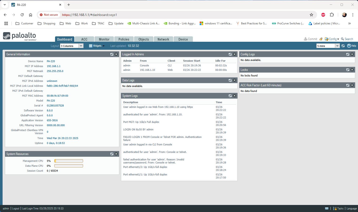
Default Management IP Address : 192.168.1.1
Default User : admin
Default Password : admin
Set Interface IP Address
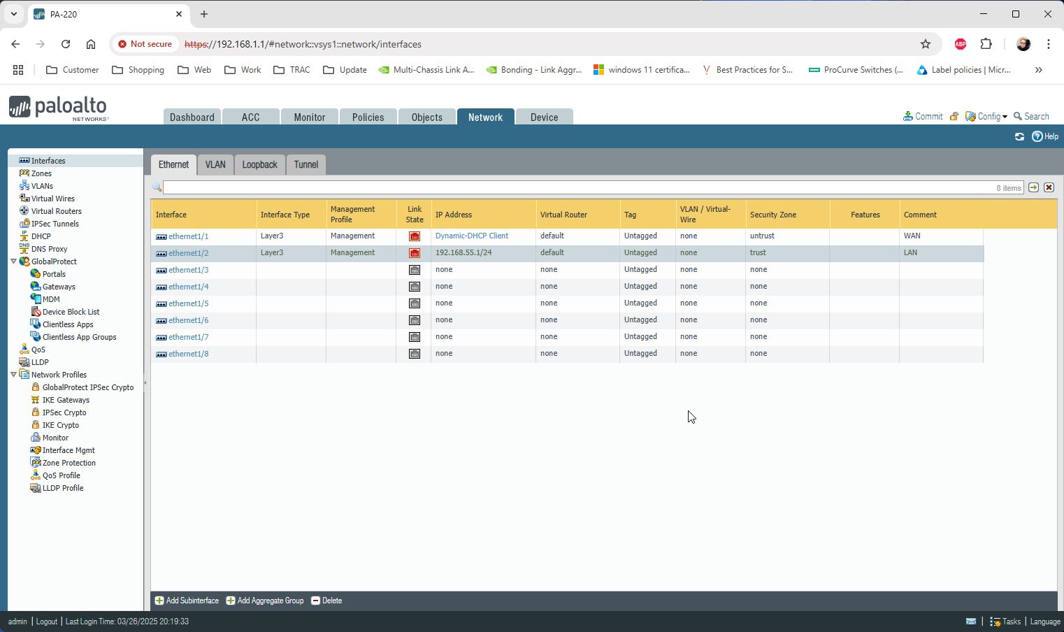
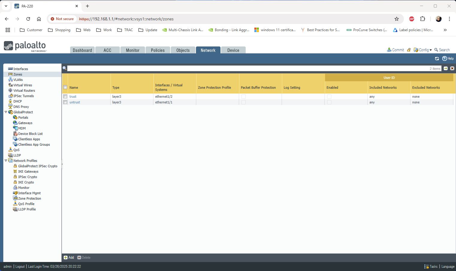
Change Zone Type และลบ Virtual Wires ออกเพราะไม่ได้ใช้
Set DHCP to LAN
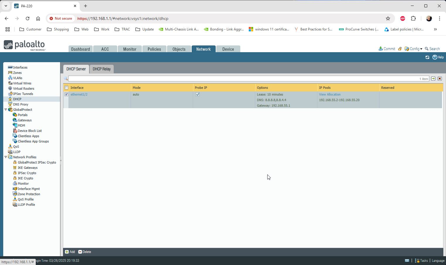
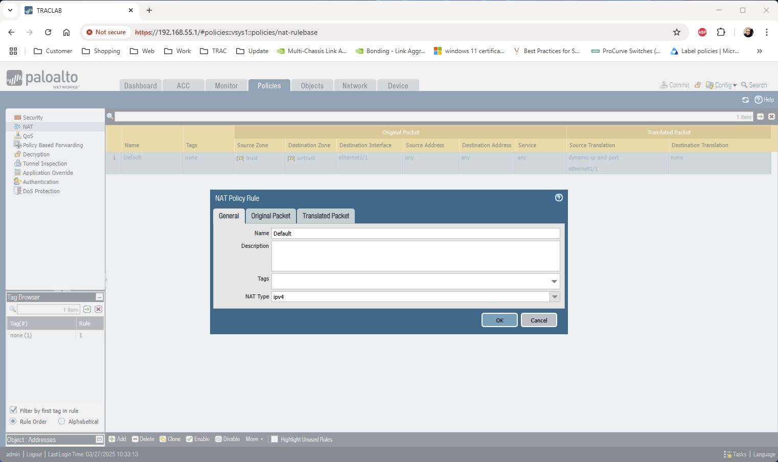
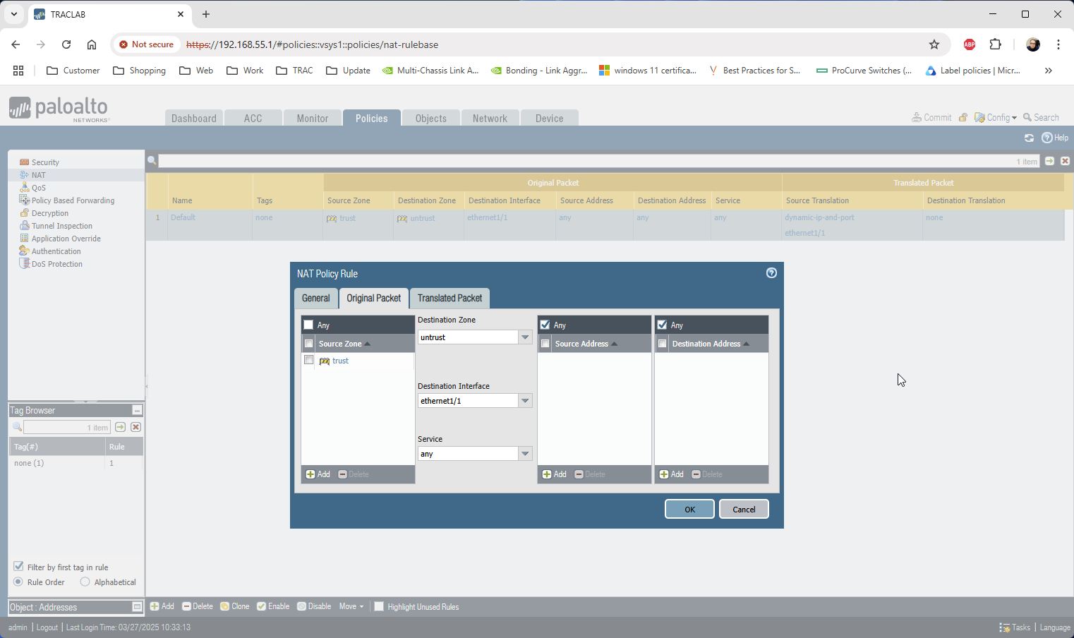
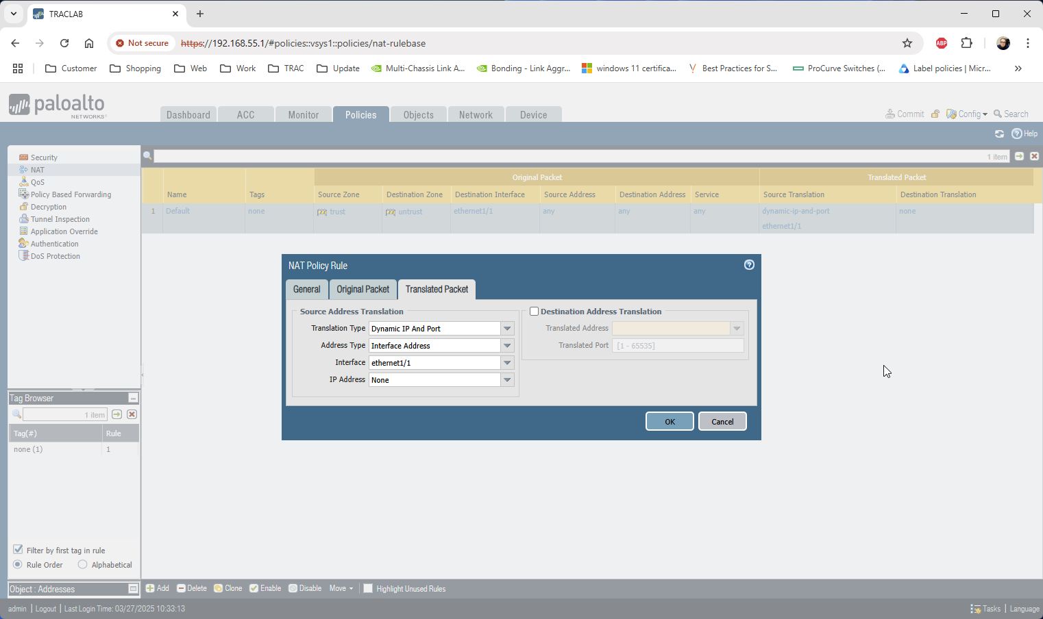
Create Default NAT from LAN to WAN
Commit to Save Config
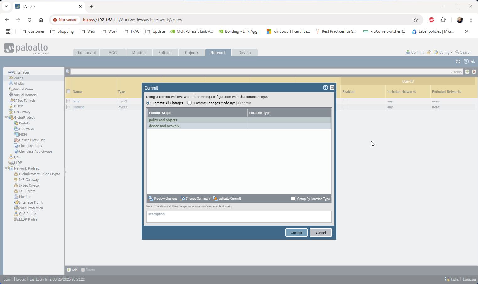
ตอนนี้ User ใช้งาน Internet ได้แล้ว
leaf01 คือ Switch 1
leaf02 คือ Switch 2
bond11 คือ uplink ไปที่ Core Switch มี 2 port คือ Port 16 ของ Switch ทั้งคู่
br_default คือ trunk vlan
peerlink คือ port ที่ Switch ทั้งคู่ใช้คุยกันเอง Port 20,21 ของ Switch ทั้งคู่
Initial Switch leaf01
nv set interface eth0 ip address 192.168.5.201/24
nv set interface eth0 ip gateway 192.168.5.1
nv set system hostname leaf01
nv set system ssh-server permit-root-login enabled
nv set system ssh-server vrf mgmt
nv set system timezone Asia/Bangkok
nv set service ntp mgmt server 3.th.pool.ntp.org iburst on
nv set interface swp1-22
nv config apply
date
Initial Switch leaf02
nv set interface eth0 ip address 192.168.5.202/24
nv set interface eth0 ip gateway 192.168.5.1
nv set system hostname leaf01
nv set system ssh-server permit-root-login enabled
nv set system ssh-server vrf mgmt
nv set system timezone Asia/Bangkok
nv set service ntp mgmt server 3.th.pool.ntp.org iburst on
nv set interface swp1-22
nv config apply
date
Config MLAG leaf01
nv set interface bond11 bond member swp16
nv set interface bond11 description Leaf-to-Spine-Connection
nv set interface bond11 bond mlag id 1
nv set interface bond11 bridge domain br_default
nv config apply
Config MLAG leaf02
nv set interface bond11 bond member swp16
nv set interface bond11 description Leaf-to-Spine-Connection
nv set interface bond11 bond mlag id 1
nv set interface bond11 bridge domain br_default
nv config apply
Config Peerlink leaf01
nv set interface peerlink bond member swp20-21
nv set mlag mac-address 22:45:20:AE:FF:AA
nv set mlag backup 192.168.5.202 vrf eth0
nv set mlag peer-ip linklocal
nv config apply
nv config save
Config Peerlink leaf02
nv set interface peerlink bond member swp20-21
nv set mlag mac-address 22:45:20:AE:FF:AA
nv set mlag backup 192.168.5.201 vrf eth0
nv set mlag peer-ip linklocal
nv config apply
nv config save
Check Status leaf01 and leaf02
nv show mlag
nv show mlag consistency-checker global
nv show interface bond11 bond mlag (status ต้องเป็น dual)
* MTU Bond11 กับ SWP ของ Bond11 ต้องเท่ากับ Switch ฝั่งตรงข้าม
เตรียม IP Address
Management IP
Switch 1 Management IP : 192.168.1.11
Switch 2 Management IP : 192.168.1.12
MLAG IP : 192.168.1.10 (Subnet เดียวกับ Switch 1,2 Management IP)
IPL IP ไม่ตรงกับ Subnet ที่มีใช้งานอยู่แล้วในบริษัท
Switch 1 IPL IP : 10.1.4.10
Switch 2 IPL IP : 10.1.4.11
Config Switch ทั้งคู่
# configure terminal
# hostname SwitchX
# interface mgmt0
# ip address 192.168.1.11 255.255.255.0
# exit
# ip route vrf mgmt 0.0.0.0/0 192.168.1.254
# ip name-server vrf mgmt 192.168.1.1
# ip domain-list domain.local
# en
# configure terminal
# lacp
# no spanning-tree
# ip routing
# protocol mlag
# dcb priority-flow-control enable force
Config IPL ทำที่ Switch ทั้งคู่ ใช้ Port ที่ Link ระหว่าง Switch หากัน
# interface port-channel 1
interface port-channel 1 ) # exit
# interface ethernet 1/35 channel-group 1 mode active
# interface ethernet 1/36 channel-group 1 mode active
# vlan 4000
vlan 4000) # exit
# interface vlan 4000
interface vlan 4000 ) # exit
# interface port-channel 1 ipl 1
# interface port-channel 1 dcb priority-flow-control mode on force
Config IPL Switch 1
# interface vlan 4000
interface vlan 4000 ) # ip address 10.4.1.10 /24
interface vlan 4000 ) # ipl 1 peer-address 10.4.1.11
interface vlan 4000 ) # exit
Config IPL Switch 2
# interface vlan 4000 on switch 2
interface vlan 4000 ) # ip address 10.4.1.11 /24
interface vlan 4000 ) # ipl 1 peer-address 10.4.1.10
interface vlan 4000 ) # exit
Config MLAG ทำที่ Switch ทั้งคู่
# mlag-vip my-mlag-vip-domain ip 192.168.1.10 /24 force
# mlag system-mac 00:00:5E:00:01:5D
# no mlag shutdown
ตัวอย่างสร้าง 3 mlag-port-chanel ทำที่ Switch ทั้งคู่
# interface mlag-port-channel 1-3
# interface mlag-port-channel 1-3) # exit
# interface ethernet 1/1 mlag-channel-group 1 mode active
# interface ethernet 1/2 mlag-channel-group 1 mode active
# interface ethernet 1/3 mlag-channel-group 2 mode active
# interface ethernet 1/4 mlag-channel-group 2 mode active
# interface ethernet 1/5 mlag-channel-group 3 mode active
# interface ethernet 1/6 mlag-channel-group 3 mode active
# interface mlag-port-channel 1-3 no shutdown